Read-Write Programmer for AT88SCXX Model SC-RWP2
User Manual
1. Introduction
The present read-write programmer is specifically designed for the development and batch release of ATMEL’s AT88SCXX series crypto & secure memories devices (SO-8 packed, DIP-8 packed and cartridge). With the read-write configuration zone and read-write user zone, the device has a range of functions such as simulated authentification (open to users who signed the NDA agreement with ATMEL only), configuration file management and off-line programming (able to program the target device independently without a personal computer). Even if the fuse is blown (FUSES=#00H), all the data and configuration files inside can be retracted with the correct Gc and password.
2. Hardware
The device hardware is shown by the following illustration.
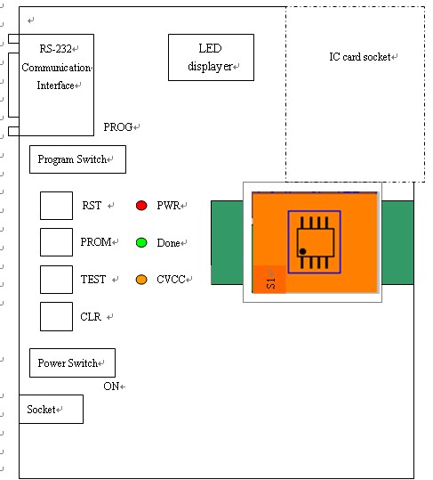
RS-232 Communication Interface: Connect the PC Communication port with DB-9 cable to install.
PROM: Switch, to PROG side before programming and switch back to the left side when complete.
RST: Button, to reset the set.
TEST: Button, to test the device configuration. Green light means OK; if it does not light up, a close examination should be conducted: for SO-8 packed device, the install direction and pin connection must be checked, for catridged device the insertion direction (contact side face up) and the contact.
CLR: Button, to clear the program counter of the set. Push the CLR and RST buttons simultaneously, then release the RST button to clear the program counter.
Power Switch: Switch to the ON side to connect power.
Socket: DC input, voltage: 8V-15V.
PWR: Light up to indicate one operation is done.
OK: Light up to indicate power is connected.
CVCC: Light up to indicate the device is charged.
Digital Display: Indicate the number of already-programed devices, which still remains in case of a power breakdown.
IC Card Socket: For catridged device, contact side faces up.
Switch Socket: S1 direction should correspond with that in the hardware illustration above.
Device Configuration: Special attention should be paid to the position of 1 foot (indicated by the point in the above hardware illustration). Push TEST button to test the configuration after finishing installation and a green light indicates correct installation.
1. Hardware Installation
Intall the device as follows:
1) Connect the RS-232 communication cable to a personal computer.
2) Connect the DC input power.
3) Switch PWR to the ON side.
2. Software Installation and Use
Click setup.exe under the Installation Directory in the disc.
Notice:
l Please make sure it is stalled in a PC with an XP or above oprating system.
l Close other application programs before installation.
l Install the hardware and connect power before starting-up the software.
3. Instruction
Please refer to ATMEL for the configurations of various register and data memory models (AT88SC0104C~25616C).
Create the Configuration File( to create the configuration file from an old configuration file )
1. Select Install Configuration File in the File menu. To reinstall, exit the the configuration zone/user zone interface.
2. Select Read-Write Configuration Zone in the Device Operation menu to configure the area, press Esc to exit.
3. Select Read-Write User Zone in the Device Operation menu to configure the area, press Esc to exit.
4. Select Save Configuration File in the File menu, enter a file name and select Save. A configuration file (demo1.dem in the Design Sample directory) has been provided in the disc.
Create Configuration File ( to create the configuration file by reading configuration file from a device )
1. Select the corresponding device model in the Device Selection menu, press Enter.
2. Install the device and select Power on in the Device Operation menu to make the device power on.
3. Select Read-Write Configuration Zone in the Device Operation menu to opeate.
4. For unfused devices, enter the password and press Test Secure Code (SC). For the fused devices, press Lead-In G/P File to lead in all the Gc and password with *.gp file. Refer to Figure 5.1 for creating such a file.
5. Press Read Configuration Zone to read the corresponding data, press Esc to exit.
6. Select Read-Write User Zone in the Device Operation menu, press Read User Partition button to read data in the present user zone. To read/modify other user zone, select the user zone first and press Esc to exit after completion.
7. Select Save Configuration File in the File menu, enter the file name and select Save.
l Reading configuration zone and user zone will delete all the previously installed configuration files.
5.4 Compare Already-Installed Configuration File
Compare the already-installed configuration files to figure out which is the freshly-installed one.
1. Select Install Configuration File in the File menu, and user configureation file will be installed and remain even in case of a power breakdown.
2. Select Compare Configuration File in the File menu.
5.5 Off-Line Programming
1. Select Install Configuration File in the File menu. The installed user configuration file will remain even in case of a power off. For already installed configuration file, the first two steps can be skipped.
2. Switch the PROG to “PROG” side.
3. Place a device to the socket of the set.
4. Press TEST to test the device. If it is correctly installed, the OK light will light up, otherwise, recheck the placement.
5. Press the PROM button.
6. When the programming operation is done, the buzzer will sound one time and the OK light will flicker once simultaneously and the counter is added 1; if the operation fails, the buffer will sound three times shortly and the OK light will not light up.
Notice:
l Make sure that the device is correctly installed, the model of the configuration file match that of the device waiting to be programed, and the secure code match that of the device waiting to be programed also.
l Fused device or device whose fuse value is not 07H cannot be programmed again.
4. Software Use
Power off and on
Press Power Connection to connect power and the “CVCC” indicator light will light up, which will go out when power breaks off.
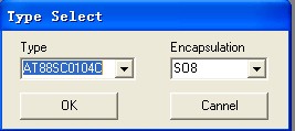
Select Device Model
Select Device Model from the Device Selection menu as follows:
Verify Security Code
1. Select Read-Write Configuration Zone from the Device Operation menu.
2. Enter the secure code in the corresponding textbox.
3. Press Test Secure Code.
If the fuse has not been blown and the secure code is correct, the configuration zone and user zone can be read or written.
Read-Write Configuration Zone
1. Operation before fuse is blown
After selecting Read-Write Configuration Zone in the Device Operation menu, the following window will pop up. Enter secure code to test the device before operation. After installing the configuration file, any reading operation will delete the input data (without changing the configuration file).
…………………………………………………………
Website of Setchief Electronics: www.setchief.com
Technical Support: 0086-20-85662866
DOWNLOAD |
